Tangential flow filtration for bioprocessing, how it works and how to scale it

Learn how tangential flow filtration works in bioprocessing, which variables matter most, and how to scale TFF from lab development to pilot and production.
Downstream basics

Tangential flow filtration, or TFF, is one of the key downstream operations used to concentrate biomolecules, clarify process streams and exchange buffers without pushing the feed directly into the membrane surface.

In a TFF system, the product circulates parallel to the membrane, which helps reduce surface build-up compared with normal flow filtration. That makes TFF especially useful in concentration and diafiltration steps where yield, process control and repeatability matter.

But good TFF performance does not depend on membrane area alone. It depends on how the whole system is designed, including pump selection, hold-up volume, pressure control, instrumentation, operating modes and the scale path from laboratory development to pilot and production.

Main use Concentration, diafiltration, clarification and buffer exchange in downstream bioprocessing.
What controls performance TMP, ΔP, flux, recirculation flow, membrane area and product behaviour.
Main membrane formats Cassette, hollow fiber and, at larger scale, ceramic or tubular options.
Selection logic Choose according to product sensitivity, recovery needs, scale and control strategy.

What is tangential flow filtration?

Tangential flow filtration is a membrane separation method in which the feed stream moves parallel to the membrane surface instead of being pushed straight through it. A portion of the liquid passes through the membrane as permeate, while the retained fraction continues in recirculation as retentate.

This cross-flow behaviour is what makes TFF so useful in bioprocessing. It helps limit cake formation and gives better control during concentration and diafiltration operations, especially when working with proteins, antibodies, viral vectors, nanoparticles or other high-value biomolecules.

laboratory tangential flow filtration system for concentration and diafiltration
At laboratory scale, TFF is often used to define the process window before scaling to pilot or production.
Why this matters

TFF is not just a filter skid. It is a controlled downstream unit operation where membrane behaviour, hydrodynamics and automation directly affect recovery, fouling and batch consistency.

How a TFF system works

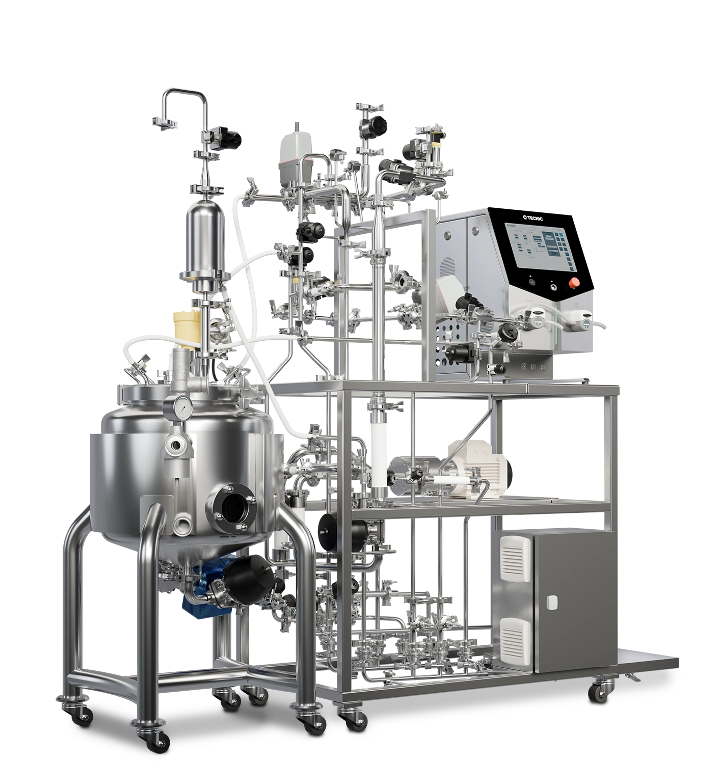
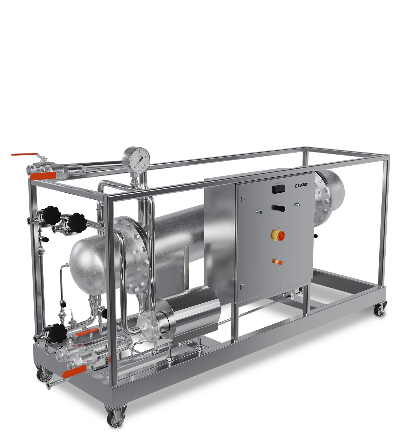
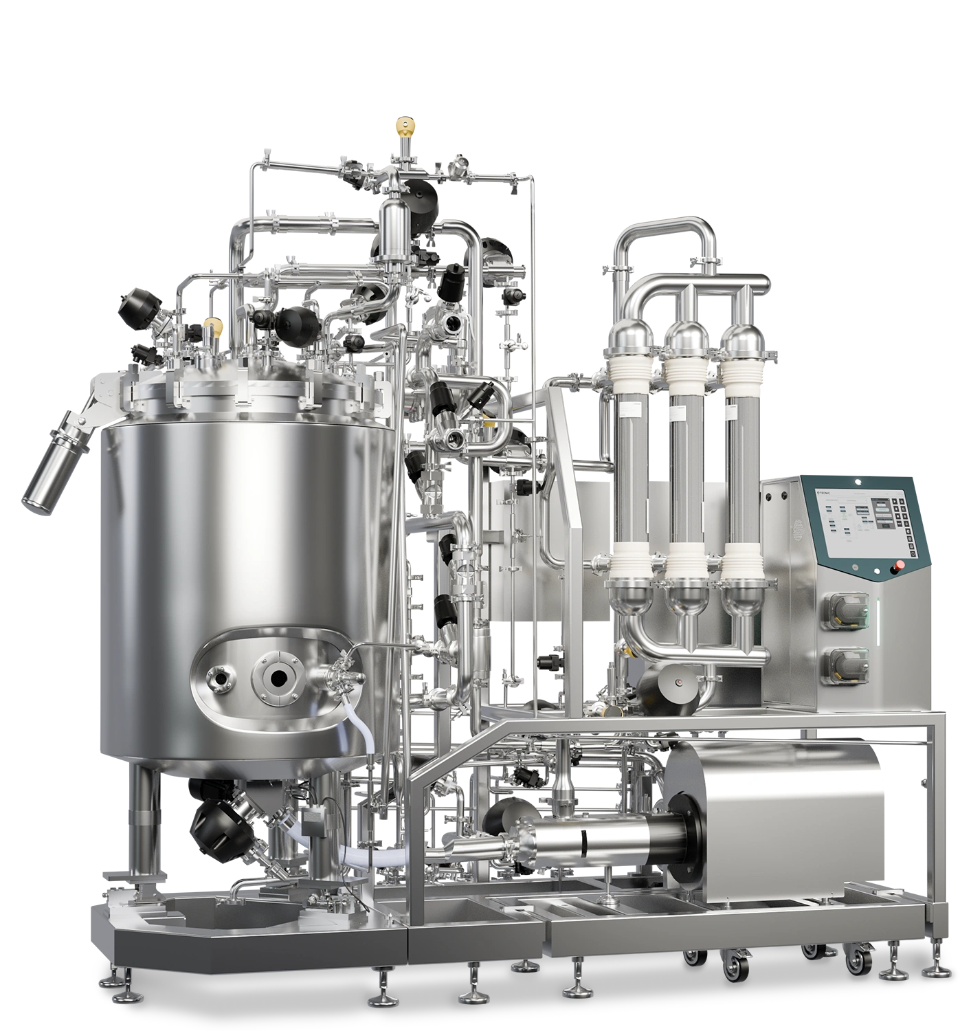
In a typical TFF loop, the product is held in a vessel or feed reservoir and recirculated across the membrane with a main pump. The membrane separates the stream into permeate and retentate, while the system keeps controlling the pressures and recirculation conditions required for stable operation.

Main functional blocks in a TFF system

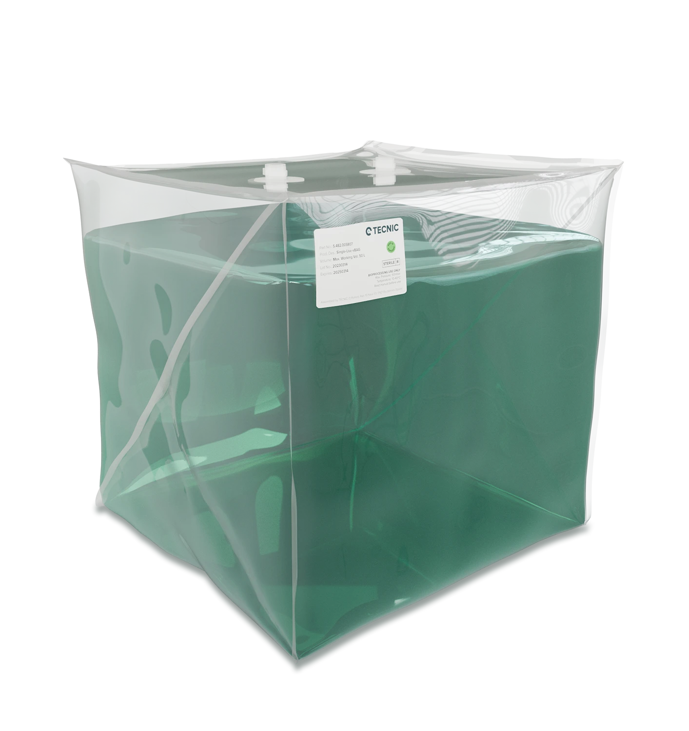
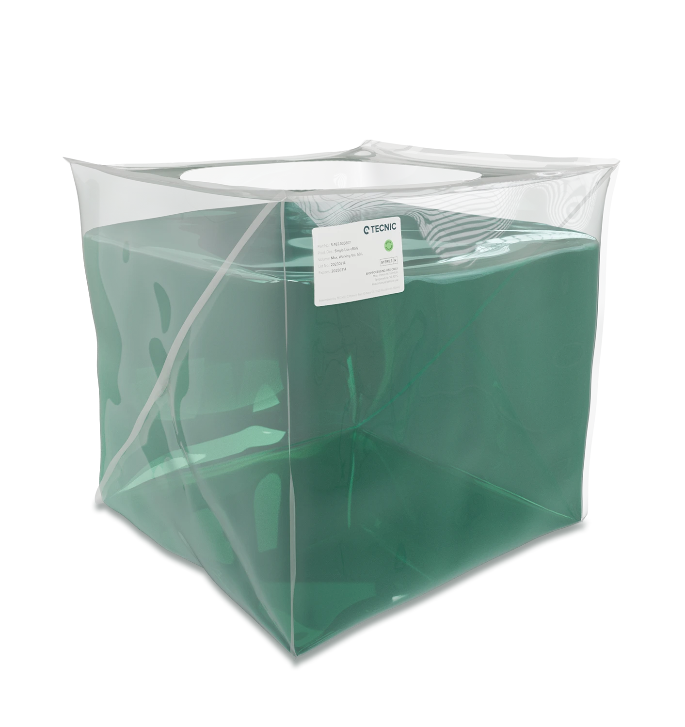
  • Product tank or reservoir, often with weighing or level control.
  • Recirculation loop with the main tangential flow pump.
  • Membrane holder or housing for cassette, hollow fiber or other module formats.
  • Pressure, flow and temperature instrumentation.
  • Permeate and diafiltration lines.
  • Control software for modes, alarms, recipes, reports and data export.

At a practical level, the process can be run in concentration mode, diafiltration mode or other supported sequences such as water flux testing, leak testing, CIP or SIP depending on platform and configuration.

Key variables that drive TFF performance

TFF performance is defined by a small group of variables that need to be understood together, not in isolation. Increasing one of them without understanding the others can improve throughput in the short term but worsen fouling, recovery or product quality.

Variable What it tells you Why it matters
TMP The effective pressure driving permeation through the membrane. Too low reduces throughput, too high can compress fouling and reduce performance.
ΔP The pressure drop along the retentate path. It reflects hydraulic load and shear behaviour across the membrane channel.
Flux The permeate flow rate per membrane area. It is one of the clearest indicators of filtration productivity and fouling behaviour.
VCF The volume concentration factor. It helps define concentration targets and process endpoints.
DV Diafiltration volumes added relative to retained volume. It defines how far the buffer exchange has progressed.
Recirculation flow The tangential flow across the membrane. It affects shear, concentration polarisation and fouling risk.

In real operation, the most common warning signs are a falling flux at constant TMP, a rising TMP needed to hold flux, or an increasing ΔP at constant recirculation flow. Those are often early indicators of concentration polarisation, gel layer formation or irreversible fouling.

Practical rule

The fastest TFF run is not always the best TFF run. Stable control within a sensible TMP and recirculation window usually protects both yield and membrane performance better than pushing the system too hard.

Membrane formats and where they fit

TFF systems are not tied to one membrane architecture. The format selected changes hold-up volume, packing density, hydraulic behaviour, cleaning strategy and scale-up logic.

Cassette membranes

Cassettes offer large membrane area in a compact footprint and are widely used for UF and DF operations. They scale well by adding area, but compression and ΔP limits must be managed carefully.

Hollow fiber membranes

Hollow fibers are often attractive when low hold-up volume and hydraulic robustness matter. They can be very useful for gentle biomolecule handling, though fouling behaviour still depends heavily on product characteristics.

Ceramic or tubular formats

At larger scale or in more demanding cleaning environments, ceramic and tubular options can make sense because of their chemical and thermal resistance. They are usually application-specific and need proper engineering review.

How to scale TFF from lab to production

A good TFF scale-up path is not only about installing more membrane area. The aim is to keep the process behaviour understandable as the system grows, which usually means preserving a sensible relationship between membrane area, recirculation flow, TMP and product sensitivity.

In practice, that means scaling by a structured platform family, not by improvisation. Lab work defines operating windows, pilot work stress-tests control and product behaviour, and production scale turns that logic into a robust automated process.

pilot tangential flow filtration system for scale-up and process optimization
Pilot TFF is where process understanding and industrial operating logic start to meet.

What should remain coherent during scale-up

  • Control logic for TMP, ΔP and recirculation flow.
  • Definition of end criteria for concentration and diafiltration.
  • Data handling, alarms and batch records.
  • Membrane format logic and product recovery strategy.
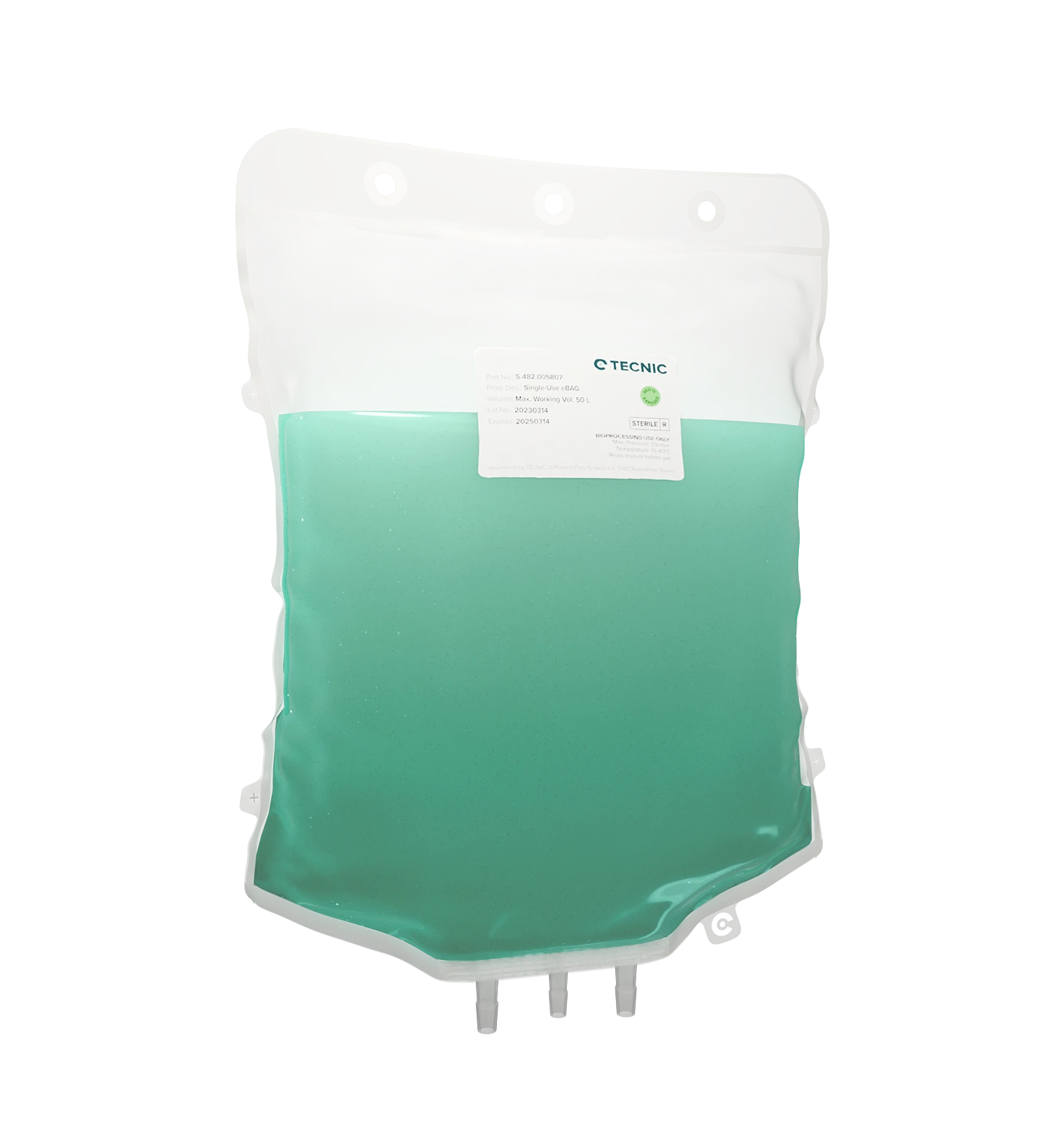
  • Cleaning, sanitisation or single-use path according to the process model.

How TECNIC TFF platforms fit the workflow

A strong TFF portfolio should not force teams to rethink the process at every scale. It should help them keep the operating logic understandable while adapting membrane area, vessel capacity and automation level to the stage of development.

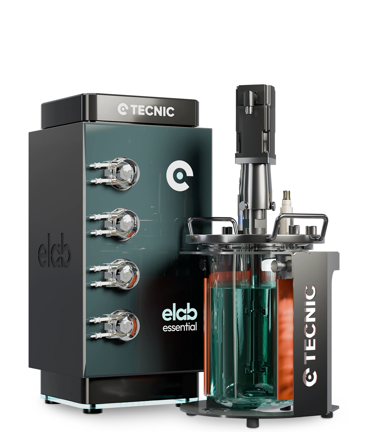
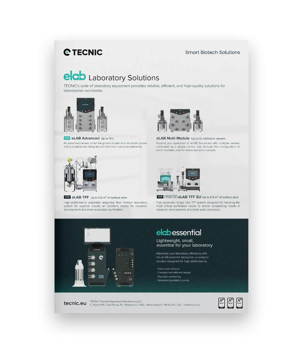
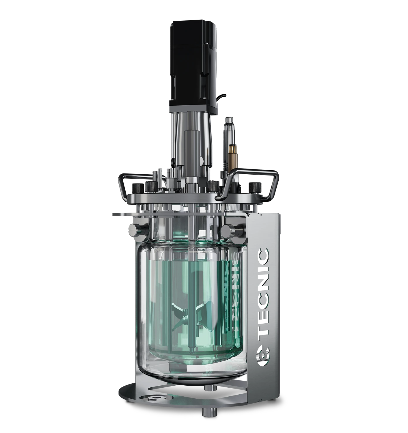
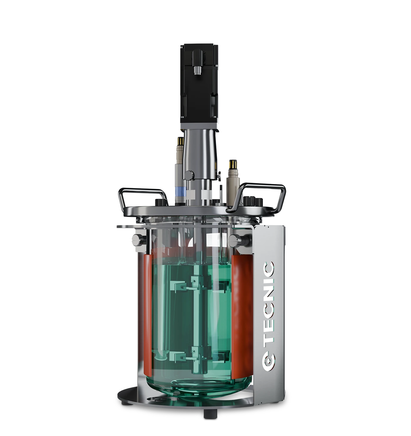
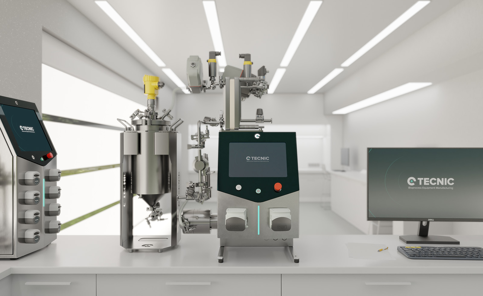
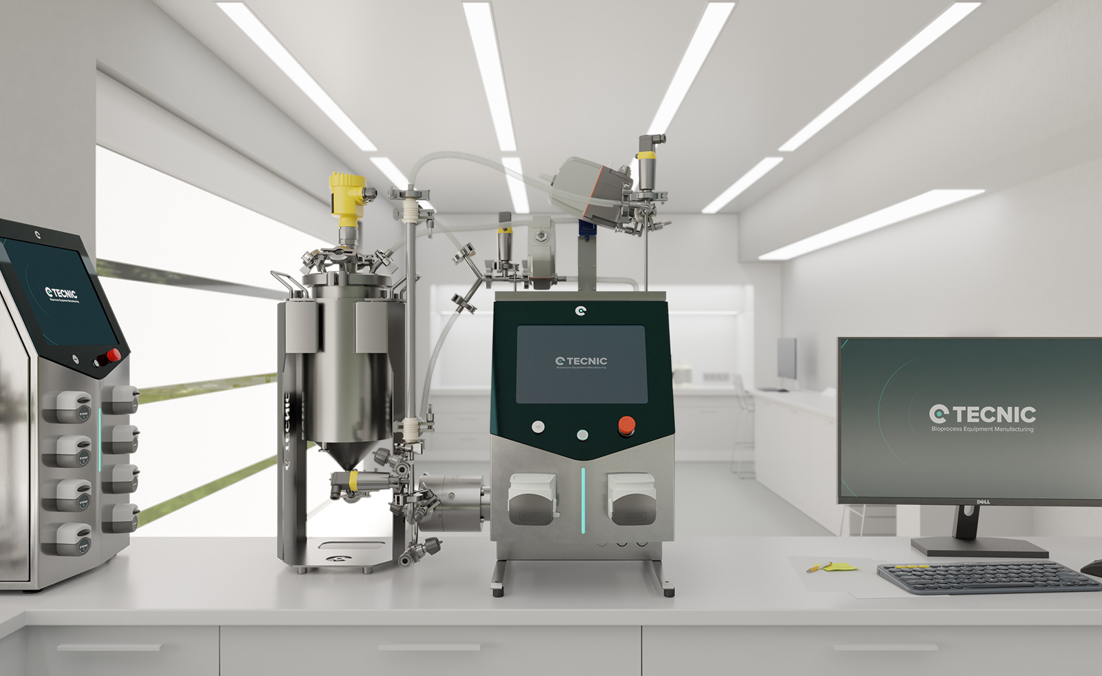
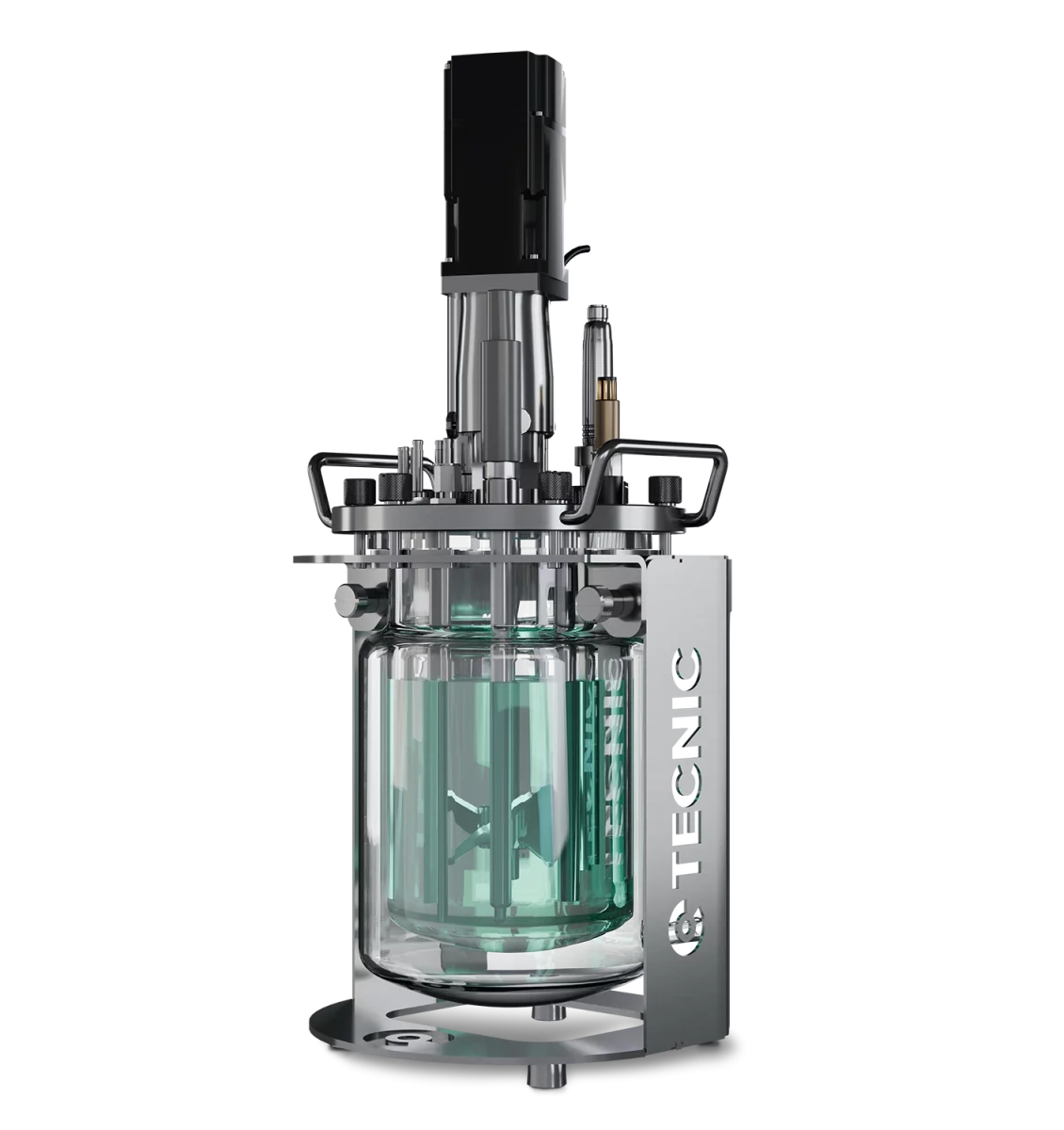
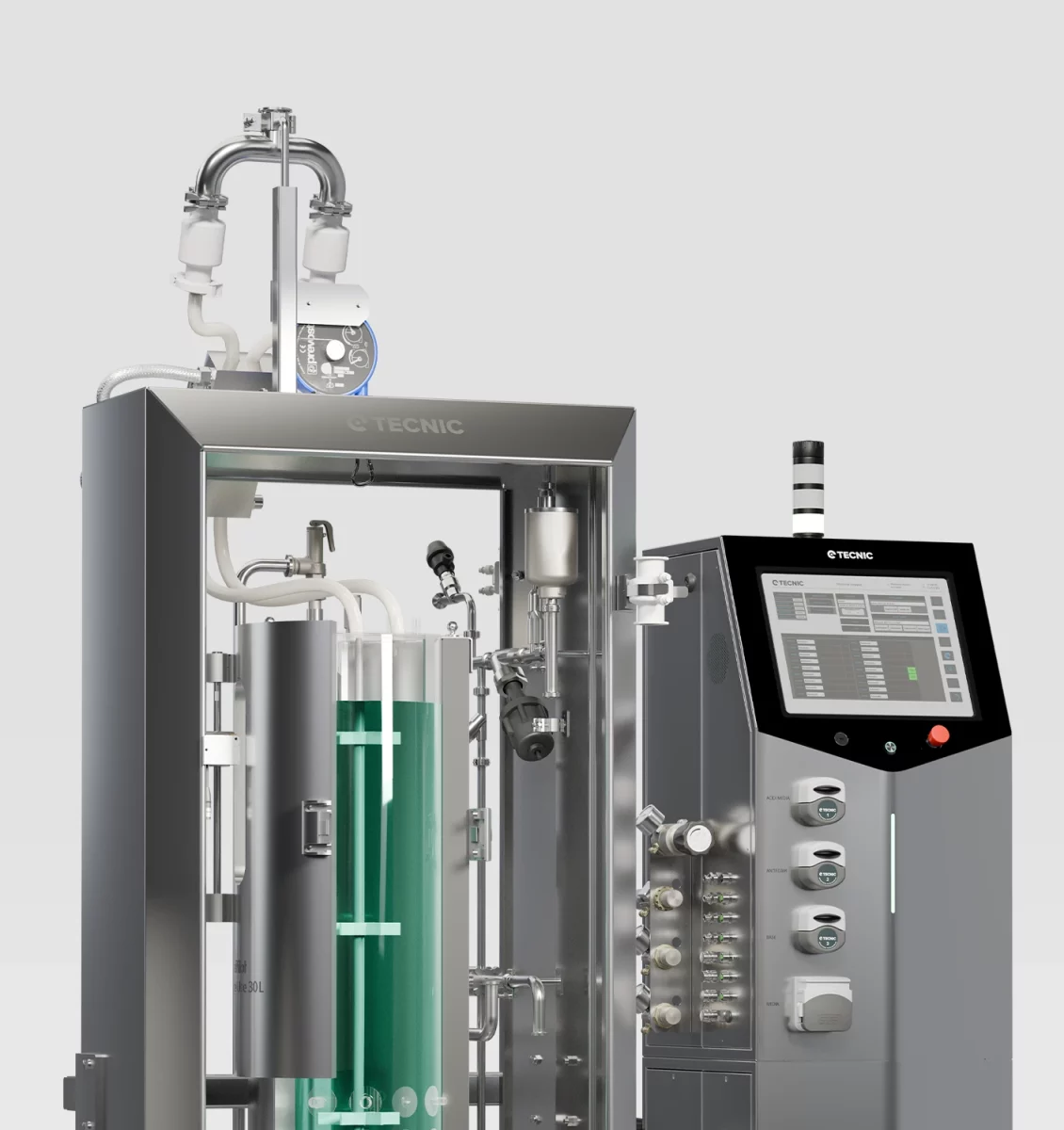
eLAB TFF for laboratory process development

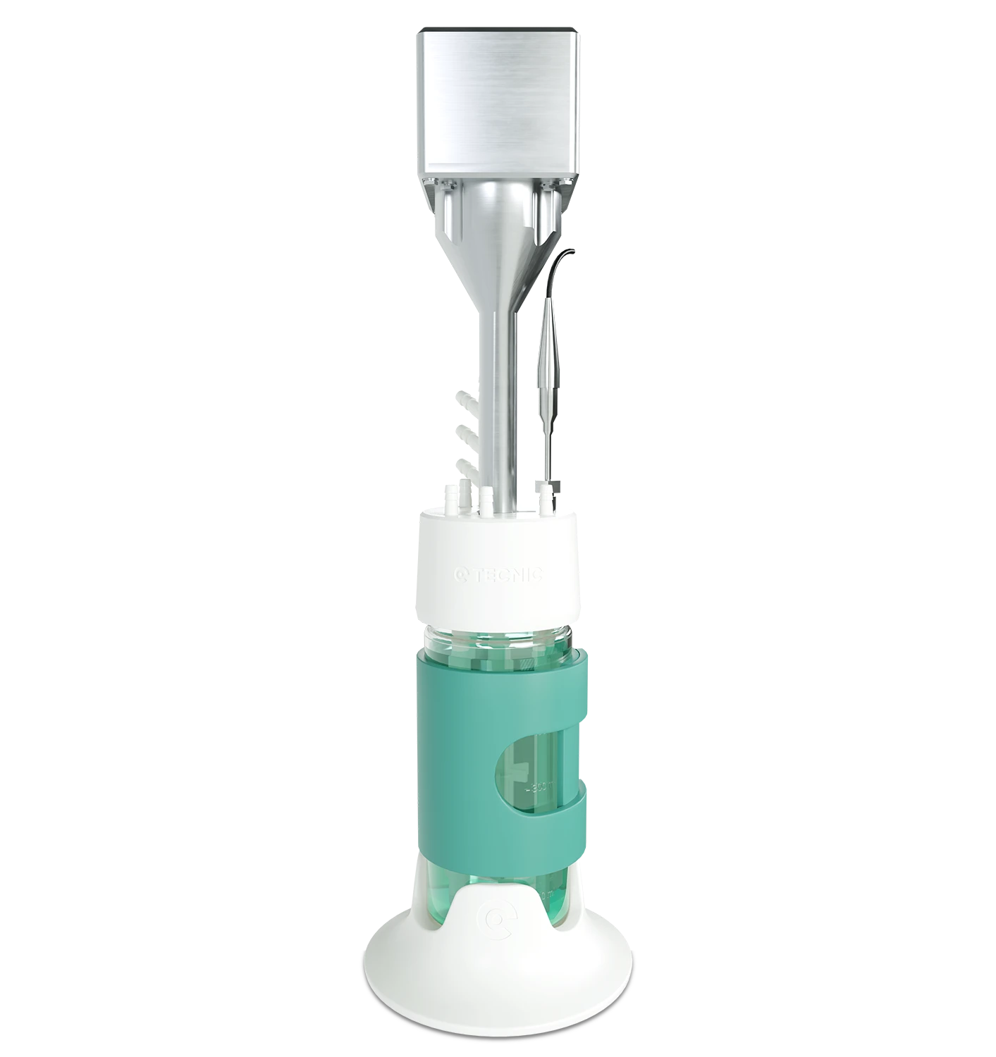
eLAB TFF is positioned for laboratory concentration, diafiltration and clarification work, where process definition, low working volumes and controlled development are the priority.

View eLAB TFF

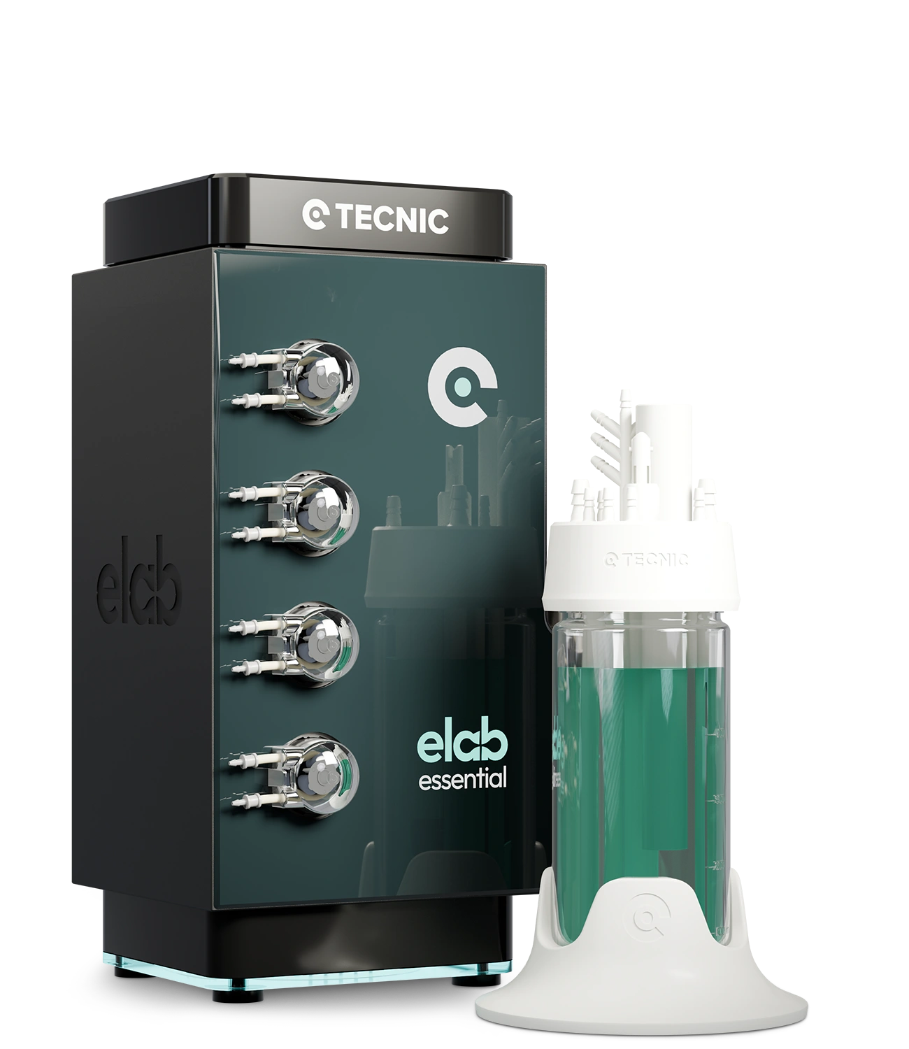
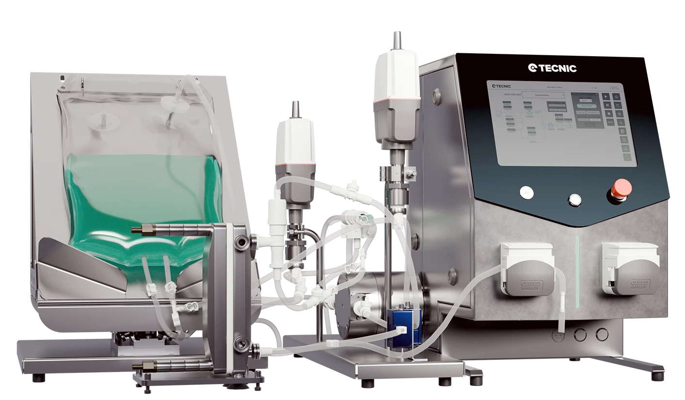
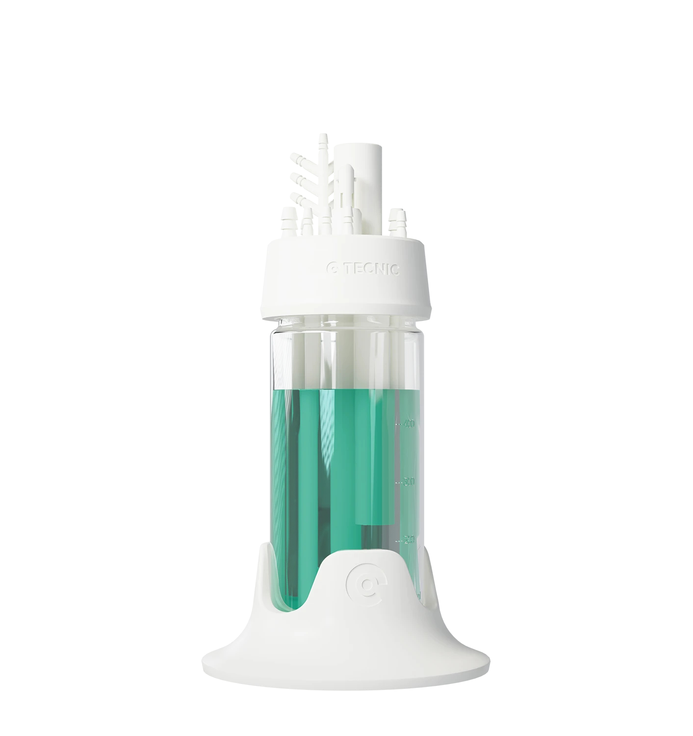
eLAB TFF SU for low hold-up and fast changeover

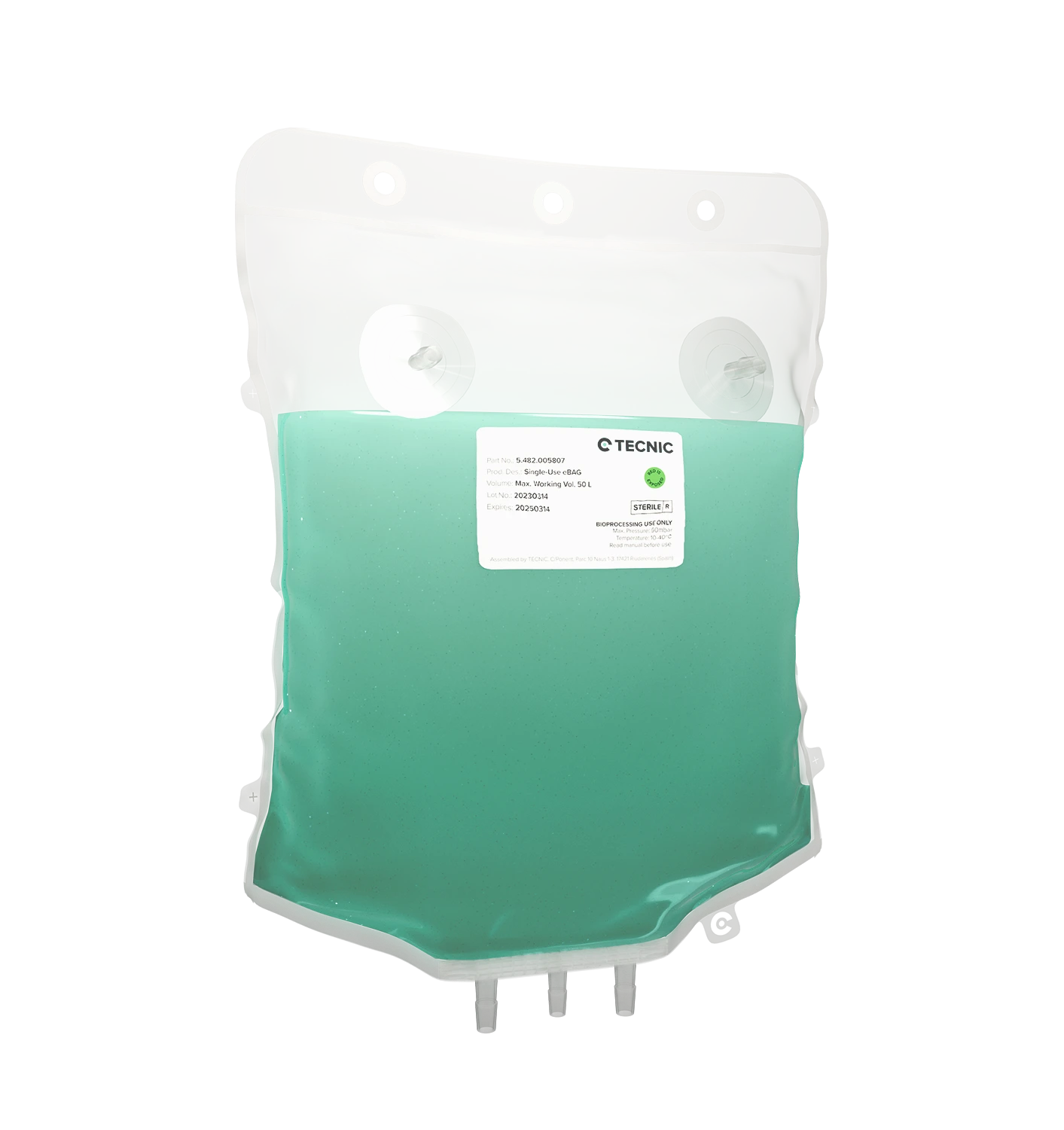
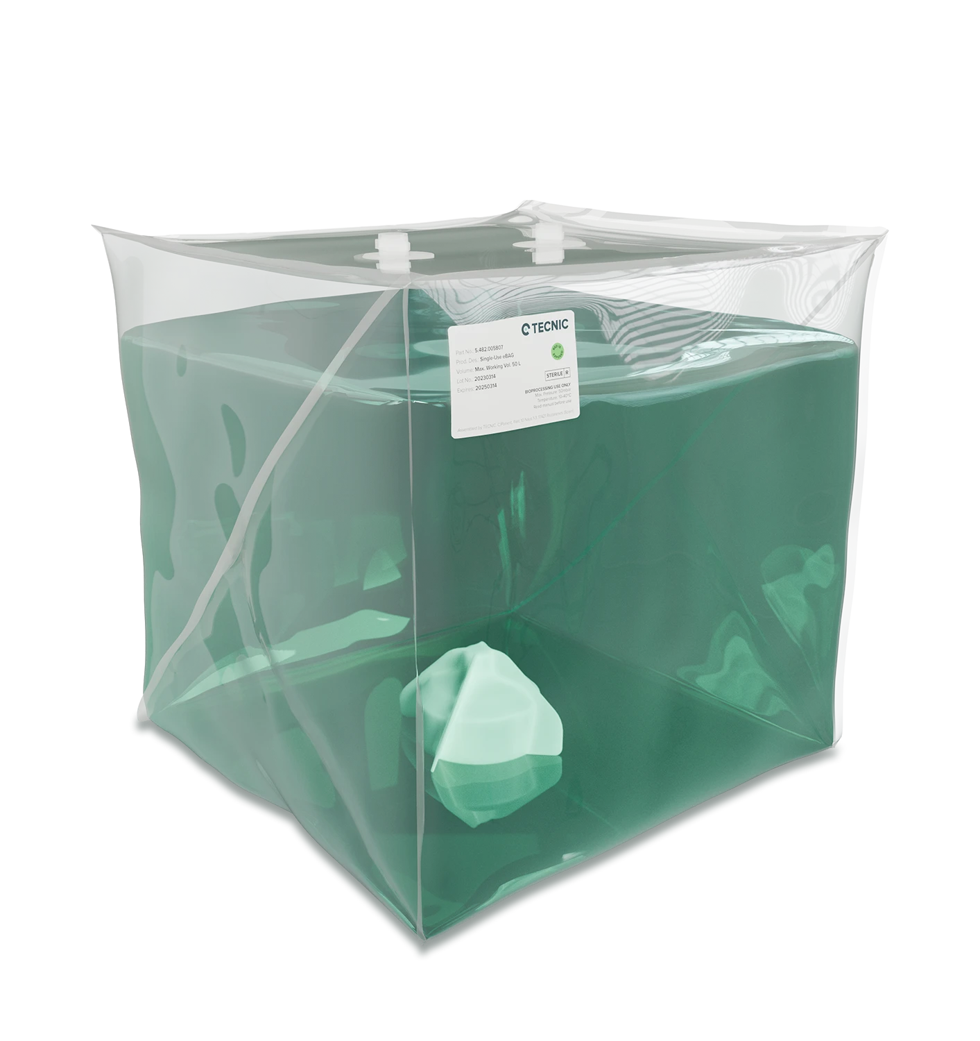
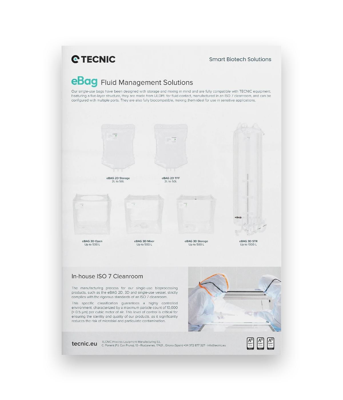
For laboratory workflows where sterility, quick setup and simplified turnover matter, eLAB TFF SU adds a single-use flow path and a compact downstream format suited to development and high-value product work.

View eLAB TFF SU

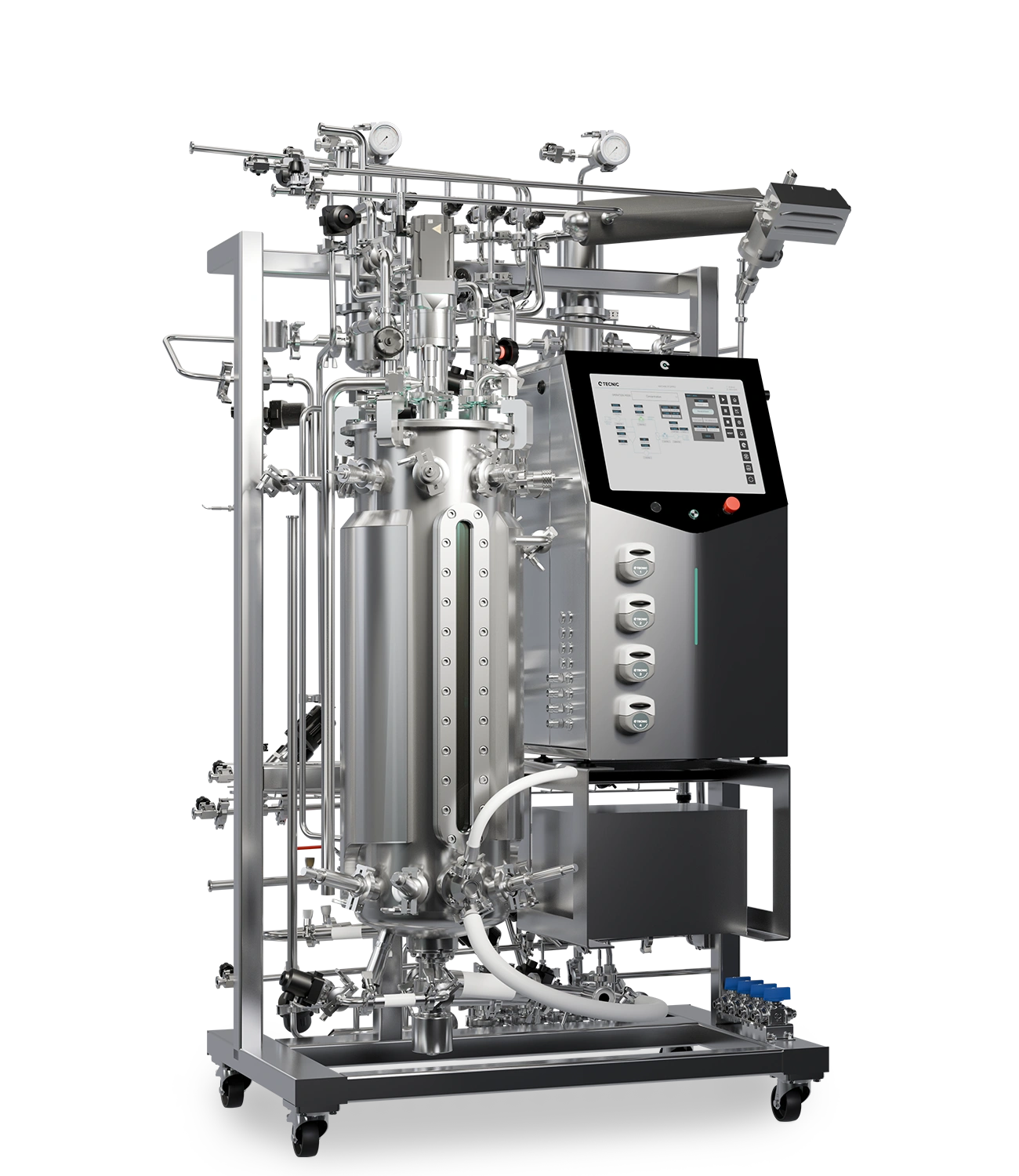
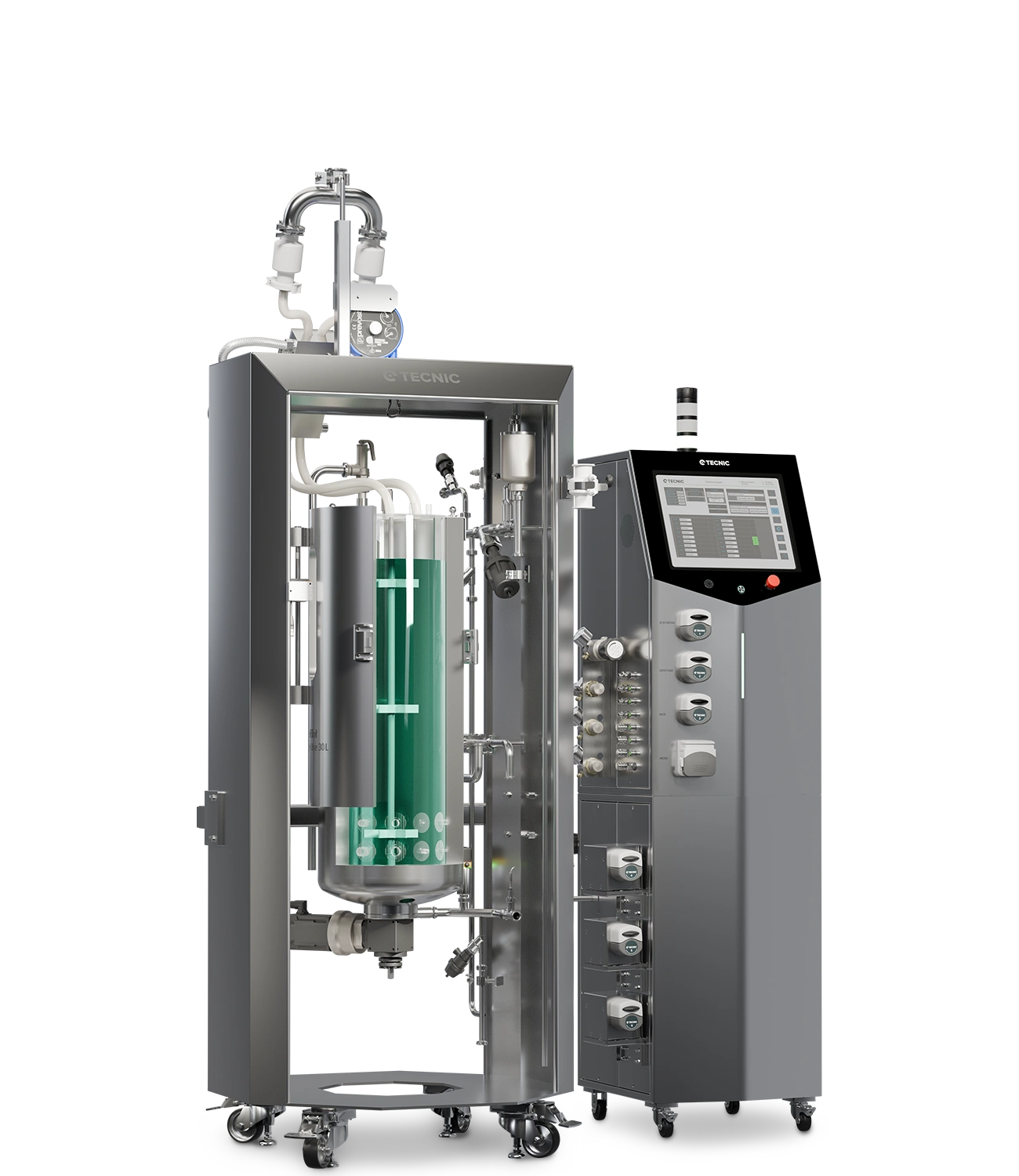
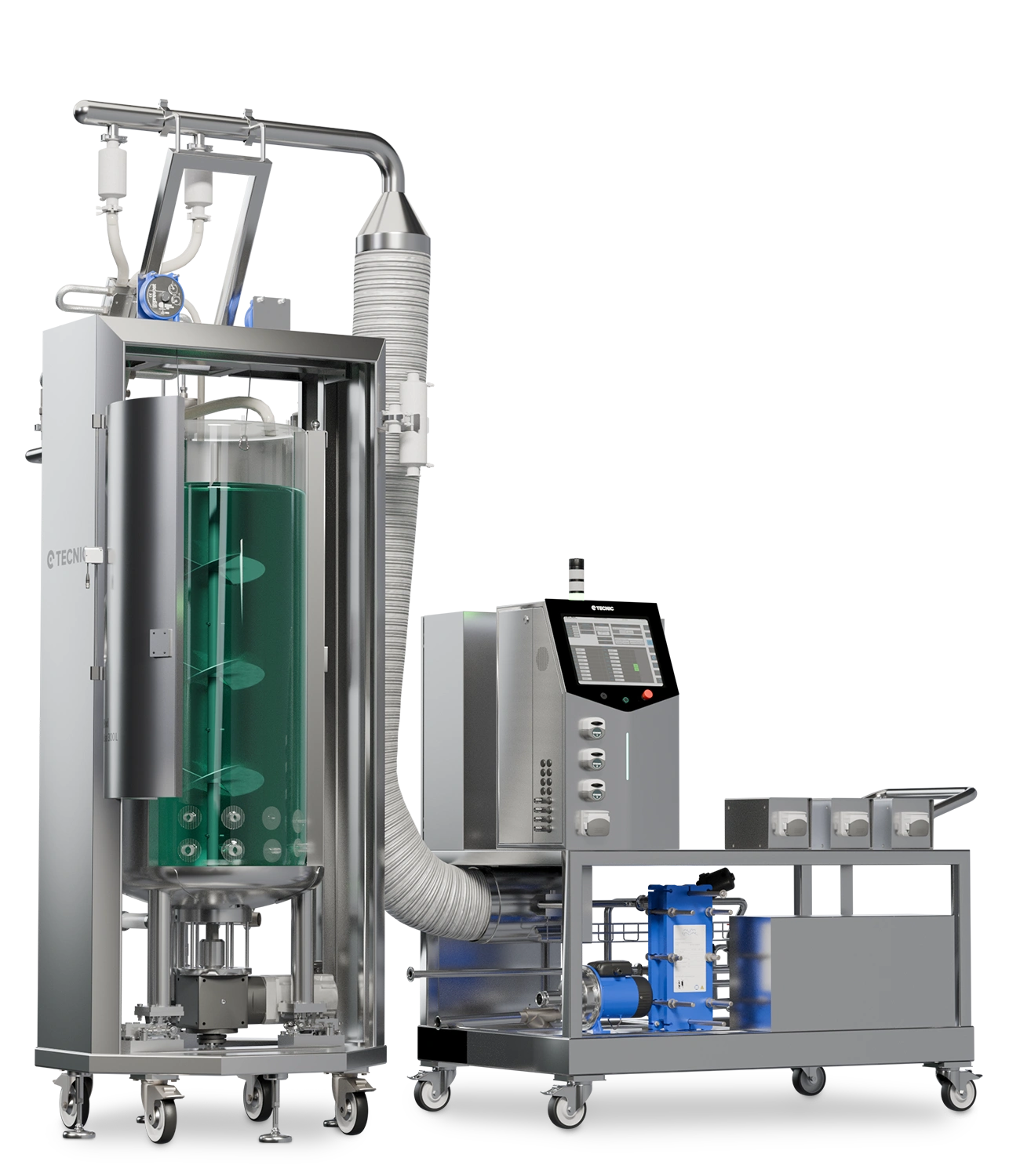
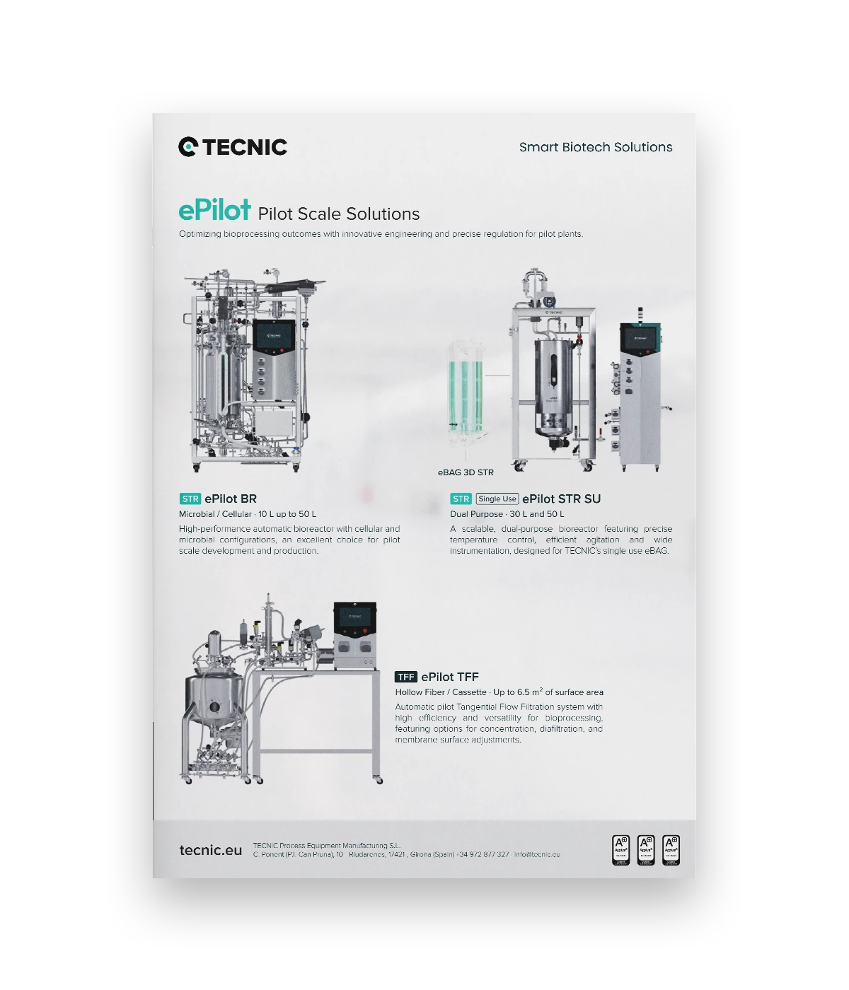
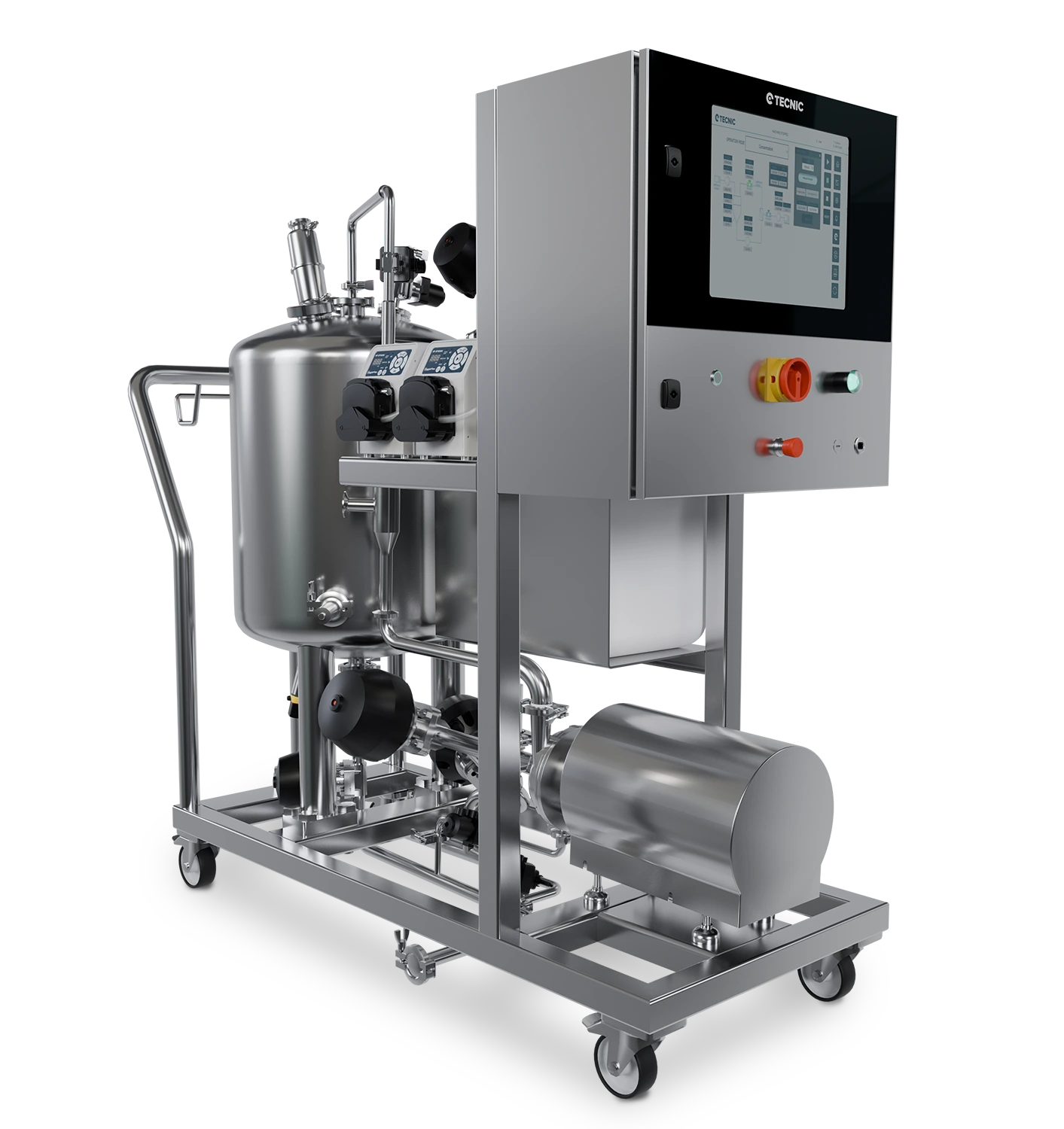
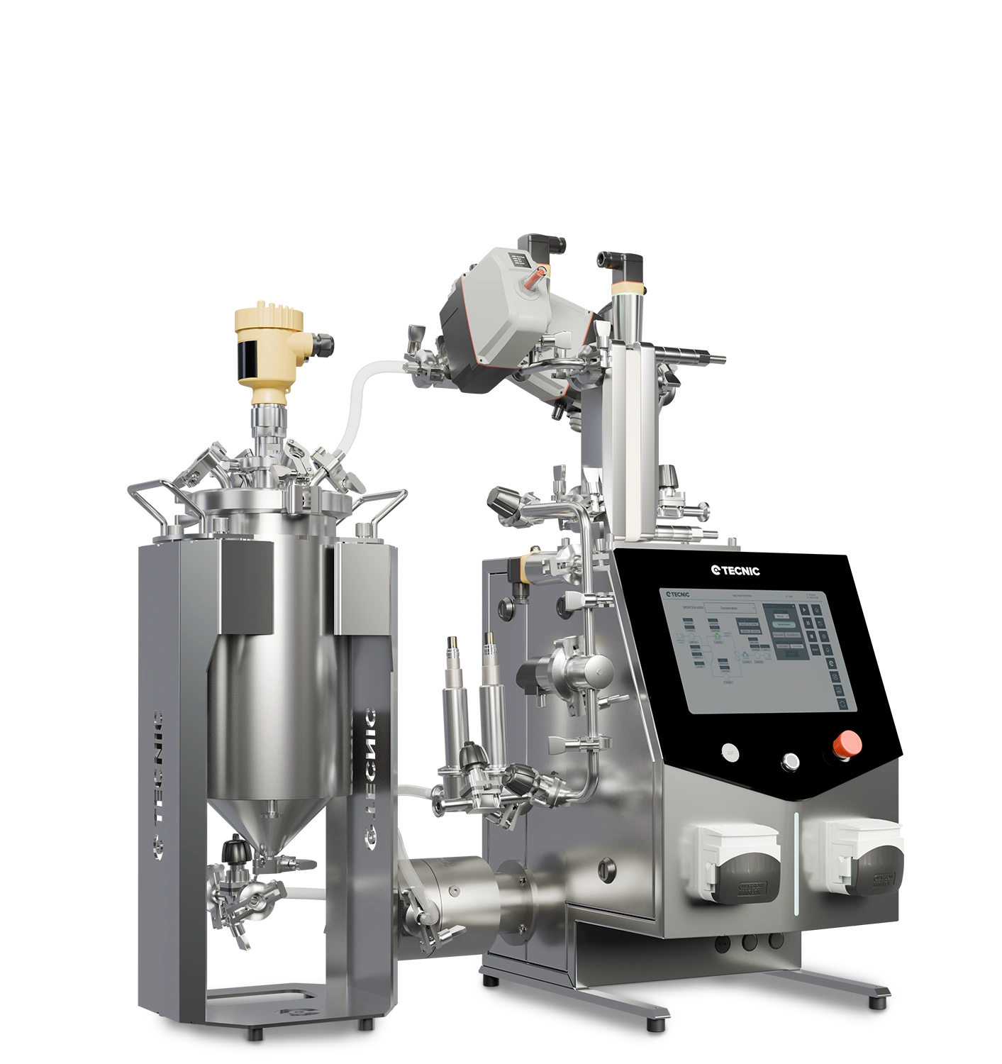
ePILOT TFF for pilot scale-up and process optimisation

ePILOT TFF is the bridge between development and larger execution, supporting concentration, diafiltration and clarification with automatic control by TMP, ΔP and flow, plus pilot-scale membrane flexibility.

View ePILOT TFF

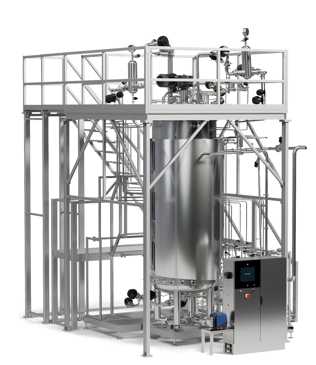
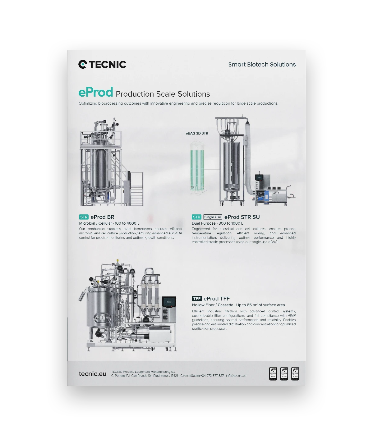
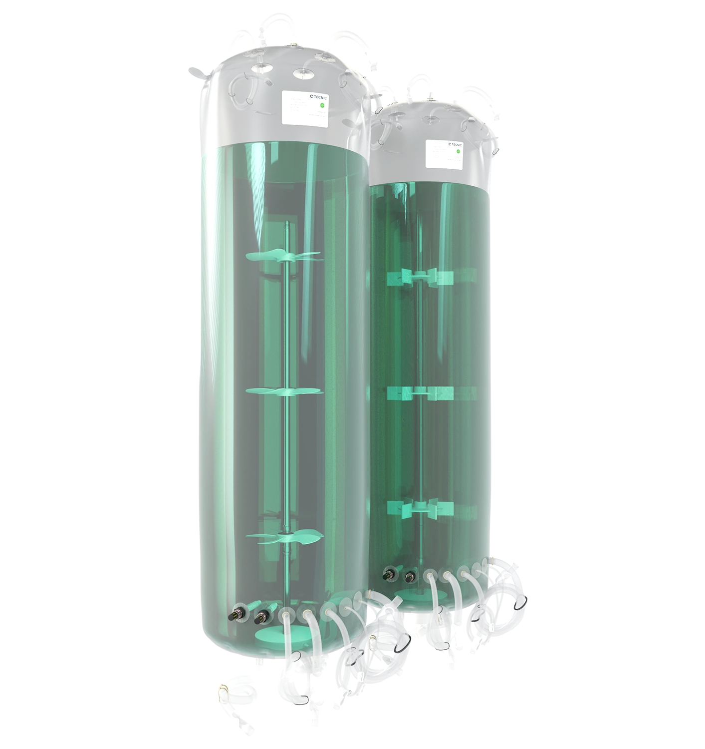
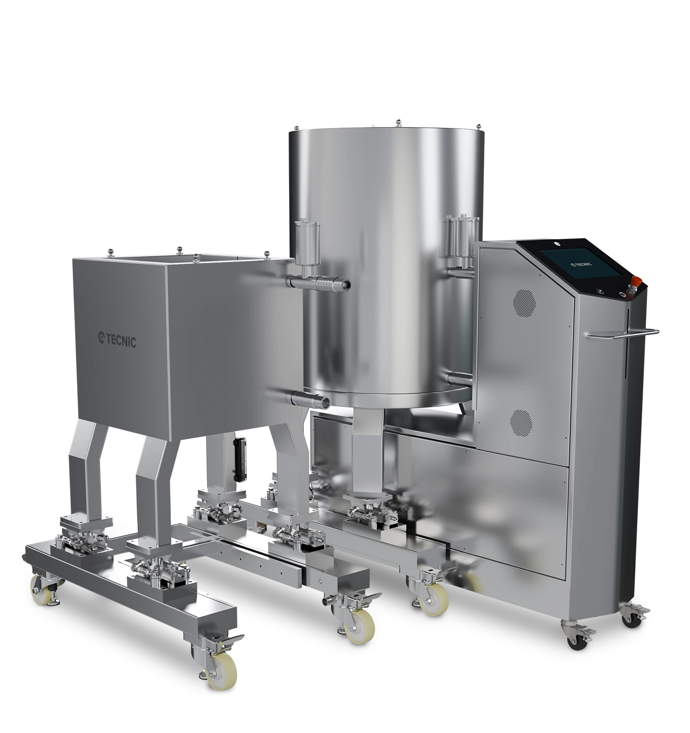
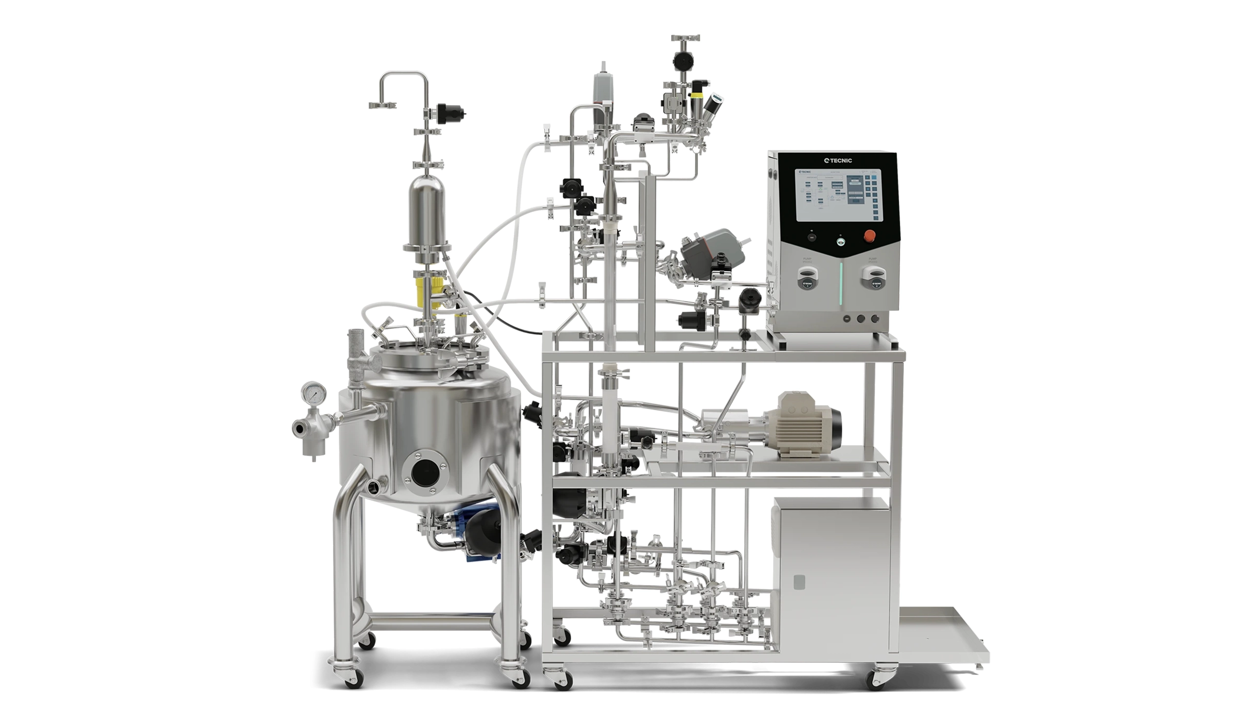
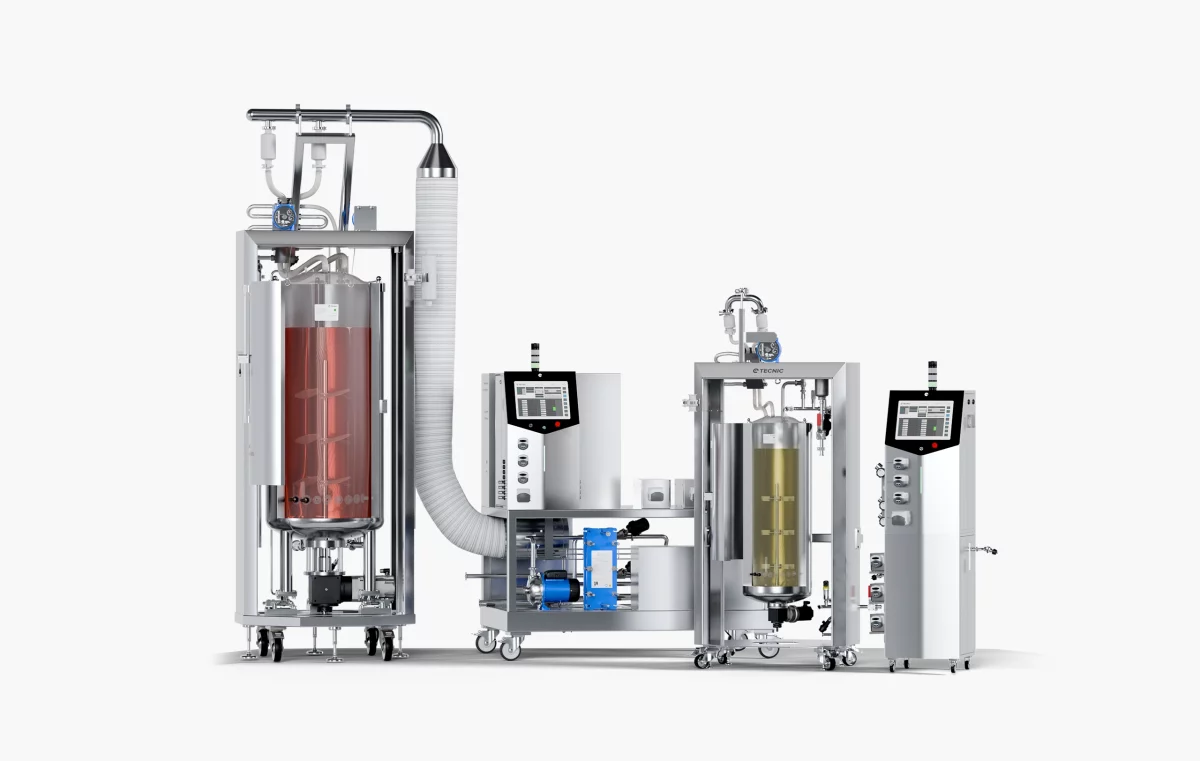
ePROD TFF for industrial downstream execution

At production scale, ePROD TFF extends the platform into industrial clarification, concentration and diafiltration, with automated operation, larger membrane areas and compatibility with cassette, hollow fiber and engineered alternatives.

View TFF systems range

industrial tangential flow filtration system for concentration and diafiltration
At production scale, TFF becomes a system-level decision involving hydraulics, automation, cleaning and documentation, not membrane area alone.
Editorial note

This product section is written as a technical bridge on purpose. It keeps the article useful for informational search intent while naturally connecting the reader with real TECNIC TFF paths.

Frequently asked questions

What is the difference between concentration and diafiltration in TFF?

Concentration removes permeate to reduce the retained volume and increase product concentration. Diafiltration adds fresh buffer while removing permeate, so the retained material stays in the system while salts or small molecules are exchanged out.

Why are TMP and ΔP both important?

TMP is the pressure driving permeation, while ΔP reflects the hydraulic load along the retentate side. Looking at both together gives a much clearer picture of how the membrane is behaving than using one alone.

Is hollow fiber always better for sensitive products?

Not automatically. Hollow fiber can offer low hold-up and good hydraulic behaviour, but the best choice still depends on the product, target recovery, fouling tendency and operating strategy.

Can the same TFF logic be scaled from lab to production?

Yes, but only if scale-up is done with attention to membrane area, recirculation flow, pressure limits, end criteria and automation logic. Good scale-up is controlled continuity, not just bigger hardware.

What should I define first when selecting a TFF system?

Start with the process objective, concentration, diafiltration, clarification or a combination, then define product sensitivity, expected membrane format, recovery target, scale and documentation needs.

Planning a TFF process from lab work to production?

Explore the TECNIC TFF range or speak with our team to review the right membrane format, scale path and control strategy for your downstream process.

Related Stories

Quote

Quote

Coming soon 

We are finalizing the details of our new equipment. Soon, we will announce all the updates. If you want to receive all the latest news about our products, subscribe to our newsletter or follow our social media channels. 

Newsletter Form

Sign Up

Stay informed about our product innovations, best practices, exciting events and much more! After signing up for our newsletter, you can unsubscribe at any time.

Newsletter Form

Cassette

We understand the importance of flexibility and efficiency in laboratory processes. That's why our equipment is designed to be compatible with Cassette filters, an advanced solution for a variety of filtration applications. Although we do not manufacture the filters directly, our systems are optimized to take full advantage of the benefits that Cassette filters offer.

Cassette filters are known for their high filtration capacity and efficiency in separation, making them ideal for ultrafiltration, microfiltration, and nanofiltration applications. By integrating these filters into our equipment, we facilitate faster and more effective processes, ensuring high-quality results.

Our equipment, being compatible with Cassette filters, offers greater versatility and adaptability. This means you can choose the filter that best suits your specific needs, ensuring that each experiment or production process is carried out with maximum efficiency and precision.

Moreover, our equipment stands out for its 100% automation capabilities. Utilizing advanced proportional valves, we ensure precise control over differential pressure, transmembrane pressure, and flow rate. This automation not only enhances the efficiency and accuracy of the filtration process but also significantly reduces manual intervention, making our systems highly reliable and user-friendly.

Hollow Fiber

We recognize the crucial role of flexibility and efficiency in laboratory processes. That's why our equipment is meticulously designed to be compatible with Hollow Fiber filters, providing an advanced solution for a broad spectrum of filtration applications. While we don't directly manufacture these filters, our systems are finely tuned to harness the full potential of Hollow Fiber filters.

Hollow Fiber filters are renowned for their exceptional performance in terms of filtration efficiency and capacity. They are particularly effective for applications requiring gentle handling of samples, such as in cell culture and sensitive biomolecular processes. By integrating these filters with our equipment, we enable more efficient, faster, and higher-quality filtration processes.

What sets our equipment apart is its 100% automation capability. Through the use of sophisticated proportional valves, our systems achieve meticulous control over differential pressure, transmembrane pressure, and flow rate. This level of automation not only boosts the efficiency and precision of the filtration process but also significantly diminishes the need for manual oversight, rendering our systems exceptionally reliable and user-friendly.

Contact General

Cellular configuration

The cellular configuration of the eLab Advanced is equipped with a pitched-blade impeller designed to support efficient mixing for cell culture processes in both laboratory development and early scale-up. The blade geometry promotes mainly axial flow, helping to distribute gases, nutrients and pH control agents uniformly throughout the vessel while keeping shear stress at a moderate level. This makes it suitable for mammalian, insect and other shear-sensitive cell lines when operated with appropriate agitation and aeration settings. In combination with the vessel aspect ratio and baffle design, the pitched blade supports stable foaming behavior and reproducible oxygen transfer, which is essential when comparing batches or transferring processes between working volumes.

Operators can fine-tune agitation speed to balance oxygen demand and mixing time without excessively increasing mechanical stress on the culture. 

Microbial configuration

The microbial configuration of the eLab Advanced is equipped with a Rushton turbine specifically designed for high-oxygen-demand processes such as bacterial and yeast fermentations. The radial-flow impeller generates strong mixing and intense gas dispersion, promoting high oxygen transfer rates and fast homogenization of nutrients, antifoam and pH control agents throughout the vessel. This makes it particularly suitable for robust microbial strains operating at elevated agitation speeds and aeration rates.

Operators can adjust agitation and gas flow to reach the required kLa while maintaining consistent mixing times, even at high cell densities. This configuration is an excellent option for users who need a powerful, reliable platform to develop and optimize microbial processes before transferring them to pilot or production scales.

Technical specifications

Materials and finishes

Typical
  • Product-contact parts: AISI 316L (1.4404), typical Ra < 0.4 µm (16 µin)
  • Non-contact parts/skid: AISI 304/304L
  • Seals/elastomers: platinum-cured silicone, EPDM and/or PTFE (material set depends on selection)
  • Elastomers compliance (depending on selected materials): FDA 21 CFR 177.2600 and USP Class VI
  • Surface treatments: degreasing, pickling and passivation (ASTM A380 and ASTM A968)
  • Roughness control on product-contact surfaces

Design conditions

Pressure & temperature

Defined considering non-hazardous process fluids (PED group 2) and jacket steam/superheated water (PED group 5), depending on configuration and project scope.

Reference design envelope
Mode Element Working pressure (bar[g]) Working pressure (psi[g]) T max (°C / °F)
ProcessVessel0 / +2.50 / +36.3+90 / 194
ProcessJacket0 / +3.80 / +55.1+90 / 194
SterilisationVessel0 / +2.50 / +36.3+130 / 266
SterilisationJacket0 / +3.80 / +55.1+150 / 302
Jacket working pressure may also be specified as 0 / +4 bar(g) (0 / +58.0 psi[g]) depending on design selection; final values are confirmed per project.

Pressure control and safeguards

Typical
  • Designed to maintain a vessel pressure set-point typically in the range 0 to 2.5 bar(g)
  • Aseptic operation commonly around 0.2 to 0.5 bar(g) to keep the vessel slightly pressurised
  • Overpressure/underpressure safeguards included per configuration and regulations
  • Pressure safety device (e.g., rupture disc and/or safety valve) included according to configuration

Agitation

Reference ranges
Working volume MU (Cell culture), reference MB (Microbial), reference
10 L0 to 300 rpm0 to 1000 rpm
20 L0 to 250 rpm0 to 1000 rpm
30 L0 to 200 rpm0 to 1000 rpm
50 L0 to 180 rpm0 to 1000 rpm

Integrated peristaltic pumps (additions)

Typical

The equipment typically includes 4 integrated variable-speed peristaltic pumps for sterile additions (acid/base/antifoam/feeds). Actual flow depends on selected tubing and calibration.

Parameter Typical value Notes
Quantity 4 units (integrated) In control tower; assignment defined by configuration
Speed 0-300 rpm Variable control from eSCADA
Minimum flow 0-10 mL/min Example with 0.8 mm ID tubing; depends on tubing and calibration
Maximum flow Up to ~366 mL/min Example with 4.8 mm ID tubing; actual flow depends on calibration
Operating modes OFF / AUTO / MANUAL / PROFILE AUTO typically associated to pH/DO/foam loops or recipe
Functions PURGE, calibration, totaliser, PWM PWM available for low flow setpoints below minimum operating level

Gas flow control (microbial reference capacity)

Reference

For microbial culture (MB), gas flow controllers (MFC) are typically sized based on VVM targets. Typical reference VVM range: 0.5-1.5 (to be confirmed by process).

Working volume (L) VVM min VVM max Air (L/min) O2 (10%) (L/min) CO2 (20%) (L/min) N2 (10%) (L/min)
100.51.55-150.5-1.51-30.5-1.5
200.51.510-301-32-61-3
300.51.515-451.5-4.53-91.5-4.5
500.51.525-752.5-7.55-152.5-7.5
O2/CO2/N2 values are shown as reference capacities for typical gas blending strategies (10% O2, 20% CO2, 10% N2). Final gas list and ranges depend on process and configuration.

Instrumentation and sensors

Typical

Instrumentation is configurable. The following list describes typical sensors integrated in standard configurations, plus common optional PAT sensors.

Variable / function Typical technology / interface Status (STD/OPT)
Temperature (process/jacket)Pt100 class A RTDSTD
Pressure (vessel/lines)Pressure transmitter (4-20 mA / digital)STD
Level (working volume)Adjustable probeSTD
pHDigital pH sensor (ARC or equivalent)STD
DO (pO2)Digital optical DO sensor (ARC or equivalent)STD
FoamConductive/capacitive foam sensorSTD
Weight / mass balanceLoad cell (integrated in skid)STD
pCO2Digital pCO2 sensor (ARC or equivalent)OPT
Biomass (permittivity)In-line or in-vessel sensorOPT
VCD / TCDIn-situ cell density sensorsOPT (MU)
Off-gas (O2/CO2)Gas analyser for OUR/CEROPT
ORP / RedoxDigital ORPOPT
Glucose / LactatePAT sensorOPT

Automation, software and connectivity

Typical

The platform incorporates TECNIC eSCADA (typically eSCADA Advanced for ePILOT) to operate actuators and control loops, execute recipes and manage process data.

Main software functions
  • Main overview screen with process parameters and trends
  • Alarm management (real-time alarms and historical log) with acknowledgement and comment option
  • Manual/automatic modes for actuators and control loops
  • Recipe management with phases and transitions; parameter profiles (multi-step) for pumps and setpoints
  • Data logging with configurable period and export to CSV; PDF report generation
Common control loops
  • Temperature control (jacket heating/cooling)
  • Pressure control (headspace) with associated valve management
  • pH control via acid/base addition pumps and optional CO2 strategy
  • DO control with cascade strategies (agitation, air, O2, N2) depending on package and configuration
  • Foam control (foam sensor and automatic antifoam addition)
Data integrity and 21 CFR Part 11

Support for 21 CFR Part 11 / EU GMP Annex 11 is configuration- and project-dependent and requires customer procedures and validation (CSV).

Utilities

Reference

Utilities depend on final configuration (e.g., AutoSIP vs External SIP) and destination market (EU vs North America). The following values are typical reference points.

Utility Typical service / configuration Pressure Flow / power Notes
Electrical EU base: 400 VAC / 50 Hz (3~) N/A AutoSIP: 12 kW; External SIP: 5 kW NA option: 480 VAC / 60 Hz; cabinet/wiring per NEC/NFPA 70; UL/CSA as required
Process gases Air / O2 / CO2 / N2 Up to 2.5 bar(g) (36.3 psi) According to setpoint Typical OD10 pneumatic connections; final list depends on package
Instrument air Pneumatic valves Up to 6 bar(g) (87.0 psi) N/A Dry/filtered air recommended
Cooling water Jacket cooling water 2 bar(g) (29.0 psi) 25 L/min (6.6 gpm) 6-10 °C (43-50 °F) typical
Cooling water Condenser cooling water 2 bar(g) (29.0 psi) 1 L/min (0.26 gpm) 6-10 °C (43-50 °F) typical
Steam (External SIP) Industrial steam 2-3 bar(g) (29.0-43.5 psi) 30 kg/h (66 lb/h) For SIP sequences
Steam (External SIP) Clean steam 1.5 bar(g) (21.8 psi) 8 kg/h (18 lb/h) Depending on plant strategy

Compliance and deliverables

Typical

Depending on destination and project scope, the regulatory basis may include European Directives (CE) and/or North American codes. The exact list is confirmed per project and stated in the Declaration(s) of Conformity when applicable.

Scope EU (typical references) North America (typical references)
Pressure equipmentPED 2014/68/EUASME BPVC Section VIII (where applicable)
Hygienic designHygienic design good practicesASME BPE (reference for bioprocessing)
Machine safetyMachinery: 2006/42/EC (until 13/01/2027) / (EU) 2023/1230OSHA expectations; NFPA 79 (industrial machinery) - project dependent
Electrical / EMCLVD 2014/35/EU; EMC 2014/30/EUNEC/NFPA 70; UL/CSA components and marking as required
Materials contactEC 1935/2004 + EC 2023/2006 (GMP for materials) where applicableFDA 21 CFR (e.g., 177.2600 for elastomers) - materials compliance
Software / CSVEU GMP Annex 11 (if applicable)21 CFR Part 11 (if applicable)
Standard documentation package
  • User manual and basic operating instructions
  • P&ID / layout drawings as per project scope
  • Material certificates and finish/treatment certificates (scope dependent)
  • FAT report (if included in contract)
Optional qualification and commissioning services
  • SAT (Site Acceptance Test)
  • IQ / OQ documentation and/or execution (scope agreed with customer)
  • CSV support package for regulated environments (ALCOA+ considerations, backups, time synchronisation, etc.)

Ordering and configuration

Project-based

ePILOT BR is configured per project. To define the right MU/MB package, volumes and options (utilities, sensors, software and compliance), please contact TECNIC with your URS or request the configuration questionnaire.

The information provided above is for general reference only and may be modified, updated or discontinued at any time without prior notice. Values and specifications are indicative and may vary depending on project scope, configuration and applicable requirements. This content does not constitute a binding offer, warranty, or contractual commitment. Any final specifications, deliverables and acceptance criteria will be confirmed in the corresponding quotation, technical documentation and/or contract documents.

Cellular configuration

The cellular configuration of the eLab Advanced is equipped with a pitched-blade impeller designed to support efficient mixing for cell culture processes in both laboratory development and early scale-up. The blade geometry promotes mainly axial flow, helping to distribute gases, nutrients and pH control agents uniformly throughout the vessel while keeping shear stress at a moderate level. This makes it suitable for mammalian, insect and other shear-sensitive cell lines when operated with appropriate agitation and aeration settings. In combination with the vessel aspect ratio and baffle design, the pitched blade supports stable foaming behavior and reproducible oxygen transfer, which is essential when comparing batches or transferring processes between working volumes.

Operators can fine-tune agitation speed to balance oxygen demand and mixing time without excessively increasing mechanical stress on the culture. 

Technical specifications

[contact-form-7 id="c5c798c" title="ePilot BR configuration questionnaire"]

Cellular configuration

The cellular configuration of the eLab Advanced is equipped with a pitched-blade impeller designed to support efficient mixing for cell culture processes in both laboratory development and early scale-up. The blade geometry promotes mainly axial flow, helping to distribute gases, nutrients and pH control agents uniformly throughout the vessel while keeping shear stress at a moderate level. This makes it suitable for mammalian, insect and other shear-sensitive cell lines when operated with appropriate agitation and aeration settings. In combination with the vessel aspect ratio and baffle design, the pitched blade supports stable foaming behavior and reproducible oxygen transfer, which is essential when comparing batches or transferring processes between working volumes.

Operators can fine-tune agitation speed to balance oxygen demand and mixing time without excessively increasing mechanical stress on the culture. 

Technical specifications

Models and working volumes

Tank

The ePlus Mixer platform combines an ePlus Mixer control tower with Tank frames and eBag 3D consumables. Tank can be supplied in square or cylindrical configurations (depending on project) to match the bag format.

Tank model Nominal volume Minimum volume to start agitation*
Tank 50 L50 L15 L
Tank 100 L100 L20 L
Tank 200 L200 L30 L
Tank 500 L500 L55 L
*Values based on agitation start interlocks per tank model. Final performance depends on the selected eBag 3D, fluid properties and configuration.

Design conditions and operating limits

Reference

Reference limits are defined for the ePlus Mixer and the Tank. It is recommended to validate the specific limits of the selected eBag 3D and single-use sensors for the customer’s process.

Element Operating pressure Maximum pressure (safety) Maximum working temperature
ePlus Mixer (control tower)ATM0.5 bar(g)90 °C
TankATM0.5 bar(g)45 °C
Jacket (if applicable)N/A1.5 barDepends on utilities / scope
The 0.5 bar(g) limit is associated with the equipment design, the circuit is protected by a safety valve. Confirm final limits on the equipment nameplate and project specification.

Materials and finishes

Typical
  • Control tower housing and frame: stainless steel 304
  • Product-contact metallic hard parts (if applicable): stainless steel 316 (defined in project manufacturing documentation)
  • Non-product-contact metallic parts: stainless steel 304
  • eBag consumable: single-use polymer (supplier dependent, gamma irradiation / sterilisation per specification)
  • Vent filters: PP (polypropylene), per component list
For GMP projects, the recommended documentation package includes material certificates, surface finish certificates (Ra if applicable) and consumable sterility/irradiation certificates.

Agitation system

Magnetic

Non-invasive magnetic agitation, the impeller is integrated in the eBag 3D Mixer format, avoiding mechanical seals. Agitation speed is controlled from the HMI, with start interlocks linked to the tank model and minimum volume.

Reference speed range
  • Typical agitation range: 120 to 300 rpm (configuration dependent)
  • Magnetic drive motor (reference): Sterimixer SMA 85/140, 50 Hz, 230/400 V, 0.18 kW
  • Gear reduction (reference): 1:5
  • Actuation (reference): linear actuator LEYG25MA, stroke 30–300 mm, speed 18–500 mm/s (for positioning)
Final rpm and mixing performance depend on tank size, bag format and process requirements.

Weighing and volume control

Integrated

Weight and derived volume control are performed using 4 load cells integrated in the tank frame legs and a weight indicator. Tare functions are managed from the HMI to support preparation steps and additions by mass.

Component Reference model Key parameters
Load cells (x4) Mettler Toledo SWB505 (stainless steel) 550 kg each, output 2 mV/V, IP66
Weight indicator Mettler Toledo IND360 DIN Acquisition and HMI display, tare and “clear last tare”
For installation engineering, total floor load should consider product mass + equipment mass + margin (recommended ≥ 20%).

Pumps and fluid handling

Standard

The platform includes integrated pumps for additions and circulation. Final tubing selection and calibration define the usable flow range.

Included pumps (reference)
  • 3 integrated peristaltic pumps for additions (acid/base/media), with speed control from HMI
  • 1 integrated centrifugal pump for circulation / transfer (DN25)
Peristaltic pumps (reference)
Parameter Reference Notes
Quantity3 unitsIntegrated in the control tower
Pump headHYB101 (Hygiaflex)Example tubing: ID 4.8 mm, wall 1.6 mm
Max speed300 rpmSpeed control reference: 0–5 V
Max flow (example)365.69 mL/minDepends on tubing and calibration
Centrifugal pump (reference)
Parameter Reference
ModelEBARA MR S DN25
Power0.75 kW
FlowUp to 42 L/min
PressureUp to 1 bar
For circulation and sensor loops, the eBag 3D format can include dedicated ports (depending on the selected consumable and application).

Thermal management (optional jacket)

Optional

Tank can be supplied with a jacket (single or double jacket options). The thermal circuit includes control elements and a heat exchanger, enabling temperature conditioning depending on utilities and project scope.

  • Jacket maximum pressure (reference): 1.5 bar
  • Thermal circuit safety: pressure regulator and safety valve (reference set-point 0.5 bar(g))
  • Heat exchanger (reference): T5-BFG, 12 plates, alloy 316, 0.5 mm, NBRP
  • Solenoid valves (reference): SMC VXZ262LGK, 1", DC 24 V, 10.5 W
  • Jacket sequences: fill / empty / flush (scope dependent)
The tank maximum temperature may depend on the thermal circuit and consumable limits. Confirm final values with the selected eBag 3D specification.

Instrumentation and sensors

Optional SU

Single-use sensors can be integrated via dedicated modules. The following references describe typical sensors and interfaces listed in the datasheet.

Variable Reference model Interface / protocol Supply Operating temperature IP
pH OneFerm Arc pH VP 70 NTC (SU) Arc Module SU pH, Modbus RTU 7–30 VDC 5–50 °C IP67
Conductivity Conducell-P SU (SU) Arc Module Cond-P SU, Modbus RTU 7–30 VDC 0–60 °C IP64
Temperature Pt100 ø4 × 52 mm, M8 (non-invasive) Analog / acquisition module Project dependent Project dependent Project dependent
Measurement ranges and final sensor list depend on the selected single-use components and project scope.

Automation, software and data

Standard + options

The ePlus SUM control tower integrates an industrial PLC and touch HMI. Standard operation supports Manual / Automatic / Profile modes, with optional recipe execution depending on selected software scope.

Software scope (reference)
  • Standard: eBASIC (base HMI functions)
  • Optional: eSCADA Basic or eSCADA Advanced (project dependent)
  • Trends, alarms and profiles, profiles up to 100 steps (depending on scope)
  • Data retention (reference): up to 1 year
Connectivity (reference)
  • Industrial Ethernet and integrated OPC server (included)
  • Remote access option (project dependent)

Utilities and facility interfaces

Typical

Installation requirements depend on jacket and temperature scope and the customer layout. The following values are typical references.

Utility Pressure Flow Connections Notes
Electrical supply N/A Reference: 18 A 380–400 VAC, 3~ + N, 50 Hz Confirm per final configuration and destination market
Ethernet N/A N/A RJ45 OPC server, LAN integration
Tap water 2.5 bar N/A 1/2" (hose connection) Jacket fill and services, tank volume about 25 L
Cooling water 2–4 bar 10–20 L/min 2 × 3/4" (hose connection) Heat exchanger and jacket cooling
Process air 2–4 bar N/A 1/2" quick coupling Used for jacket emptying
Drain N/A N/A 2 × 3/4" (hose connection) For draining
Exhaust N/A N/A N/A Optional (depending on project)
Stack light (optional) N/A N/A N/A 3-colour indication, as per scope
During FAT, verify in the installation checklist that the available utilities match the selected configuration and scope.

Documentation and deliverables

Project-based

Deliverables depend on scope and project requirements. The following items are typical references included in the technical documentation package.

  • Datasheet and user manual (HMI and system operation)
  • Electrical schematics, PLC program and backup package (scope dependent)
  • P&ID, layout and GA drawings (PDF and/or CAD formats, project dependent)
  • Factory Acceptance Test (FAT) protocol and FAT report (as per contract)
  • Installation checklist
  • Material and consumable certificates, as required for regulated projects (scope dependent)
On-site services (SAT, IQ/OQ) and extended compliance packages are optional and defined per project.

Ordering and configuration

Contact

The ePlus Mixer scope is defined per project. To select the right tank size, bag format, sensors and optional jacket and software, please share your URS or request the configuration questionnaire.

The information provided above is for general reference only and may be modified, updated or discontinued at any time without prior notice. Values and specifications are indicative and may vary depending on project scope, configuration and applicable requirements. This content does not constitute a binding offer, warranty, or contractual commitment. Any final specifications, deliverables and acceptance criteria will be confirmed in the corresponding quotation, technical documentation and/or contract documents.

Operating windows microbial vs. cell culture

The operating range depends on the volume, gas configuration and impeller type. Typical performance references and operating parameters for both applications are summarised below (guideline values; final performance depends on medium, antifoam, geometry and aeration strategy).

Performance and parameters:

Indicative operating windows for cellular and microbial processes. Final values depend on bag configuration, impellers, aeration strategy and process targets.

Application

Cell culture

Agitation (rpm)

300: 0–450
1000: 0–300

Tip speed (m/s)

0.4–1.8

P/V (W/m³)

80–200

kLa (h⁻¹)

20–30

Application

Microbial

Agitation (rpm)

300: 0–450
1000: 0–300

Tip speed (m/s)

1.5–5.0

P/V (W/m³)

1,000–5,500

kLa (h⁻¹)

150–330

Typical gas line ranges by model and application. Installed ranges and gas setup depend on selected options and project scope.

Gas

Process air

Typical range (Ln/min)

300 L: 20–300 (up to 600 depending on configuration)
1000 L: 20–1000 (up to 2000 depending on configuration)

Main use

Aeration by sparger / mixing

Notes by application

Microbial: primary. 

Cellular: DO support.

Gas

Oxygen (O₂)

Typical range (Ln/min)

300 L: 2–30 (up to 600 depending on configuration)
1000 L: 2–100 (up to 2000 depending on configuration)

Main use

DO enrichment and cascade

Notes by application

Microbial: frequent. Cellular: cascade at DO set point.

Gas

Carbon dioxide (CO₂)

Typical range (Ln/min)

300 L: 2–30 (typical) / 10–150 (depending on configuration)
1000 L: 2–100 (typical) / 10–500 (depending on configuration)

Main use

pH control / CO₂ balance

Notes by application

Cellular: standard. Microbial: optional.

Gas

Overlay (air or O₂)

Typical range (Ln/min)

300 L: 10–150
1000 L: 10–500

Main use

Headspace scavenging / gas control

Notes by application

Cellular: standard. Microbial: optional.

Note: the exact flow and gas ranges installed depend on the model and the options purchased.


Multi Use Bioreactors

Single Use Bioreactors

Multi Use TFF Systems

Single Use TFF Systems

Single-use bioprocess bags (2D and 3D)

Designed to enhance our bioprocess solutions

Versatile and reliable bioreactor vessels for bioprocessing

Versatile and reliable bioreactor vessels for bioprocessing